The EnerPHit Standard applied to large, complex existing buildings
Author: Steven Stenlund, BRE
Introduction
The Passive House Standard often cannot be feasibly achieved in existing buildings due to various difficulties as a direct consequence of the existing structure and orientation etc. Refurbishment to the EnerPHit Standard using Passive House components for all relevant structural elements in such buildings leads to extensive improvements with respect to thermal comfort, structural integrity, cost-effectiveness and energy requirements.
In terms of the UK EuroPHit case study building, Wilmcote House, it was decided that the first step would be to thermally upgrade the walls, windows and roof to a standard that will achieve a maximum specific heating demand of not more than 20 kWh/(m2.a) for a warm-temperate climate.
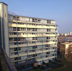
Wilmcote House, built in the 1960s and owned by Portsmouth City Council, is a large residential building containing 100 three bedroom maisonettes above 7 ground floor one bedroom flats (and other ancillary accommodation) arranged in three towers linked with common stair cores. Due to weather related issues because of its elevation and close proximity to the coast, the structure is in need of significant repairs.
The decision to pursue a step-by-step approach to achieving the EnerPHit Standard allows for the provision of external wall and roof insulation and replacement glazing to be installed alongside the structural repairs, thus reducing overall costs.
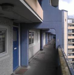
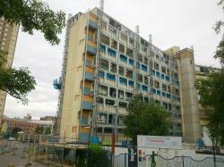
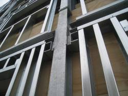
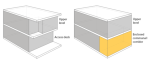
The main feature of the external wall insulation is the enclosure of the external balcony approach to the upper floor dwellings. It was decided that to attempt to maintain the existing external balcony approaches to each property would lead to many difficult construction details that would cause many issues with regards to both achieving low levels of thermal bridging and a highly airtight building. In essence this has led to a designed ‘exoskeleton’ of steelwork being provided to encapsulate the entire building into which external wall insulation is provided in numerous layers to ensure that thermal bridging caused by the main steel structure is kept to a minimum level.
Additionally, all of the existing structure is contained within the thermal envelope ensuring that the likelihood of further decay in future would be minimised, providing an extended period of longevity for the building. However due to the scale of the proposed steel enclosure it was still necessary to provide structural stability via steelwork tied back through to the existing concrete framing, and thus to some degree there is significant penetrations at least part way through the external insulation.
The refurbishment works proceeded with the challenge of not being able to move residents out of the building during the construction works, due to the shortage of other 3 bedroom homes within the Council’s housing stock.
Detailed design and implementation
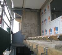
Works commenced to Block A during 2015, and by September the steelwork exoskeleton had been erected to enclose the balcony approaches to each entry level to all properties.
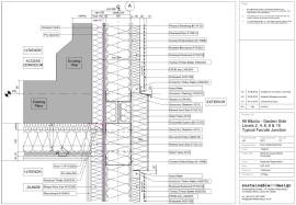
The detailed drawing above provides an indication of how complex the existing structure is and how a new insulated façade was provided. In the section, the tie-back steel channels are shown as dashed lines. As the the main steelwork is positioned within the insulation build-up, it was also necessary to provide insulation to the underside of the existing concrete walkway even though the walkway would become enclosed within the thermal envelope as the steel tie-back channels would act as a significant thermal bridge.
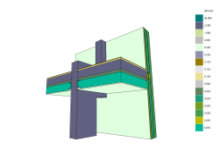
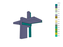
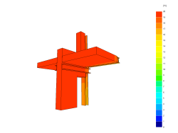
Thermal modelling was used to ensure the level of heat flow was minimised and also quantified for inclusion with the PHPP models. The following series of images were extracted from the TRISCO v12 software used for the 3D thermal bridging analysis. The sequence shows the full model build-up including all materials present, which is followed by an image where the majority of materials are ‘clipped’ from view (although they remain in the model) and finally the surface temperatures are shown for the materials (concrete and steelwork) on view. The heat flow through the steelwork can clearly be seen, however due to the presence of insulation to the underside of the concrete walkway, this is reduced to an insignificant level.
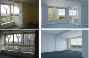
The additional benefit of providing the steel exoskeleton is that the living accommodation on the upper floors (between entry levels), where extended outwards up to the new external wall line, provides for an enlarged lounge and a sun-room. This additional private space can be utilised for clothes drying or other uses in-lieu of the now removed balconies.
The set of images below show how this additional space was first designed and then constructed.
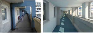
Although the provision of the new external wall brought many benefits to the overall design of the building, there have been secondary consequences that have had to be addressed. Before the external wall was built, the kitchen windows opened directly onto the access walkways. However, with the introduction of enclosed walkways the kitchen windows had to be replaced with fixed fire rated window units allowing for a protected means of escape in event of a fire. It was also necessary to provide ‘purge’ ventilation to the kitchens using intermittent extract fans (in addition to the MVHR ventilation) with ducting through to the external to purge pollutants. This did pose a challenge to achieving the airtightness requirements of the building but a solution was found through fitting an in-line damper within the extract ductwork so when the intermittent fans were not in use, the ductwork would be sealed and airtight.
Concluding remarks
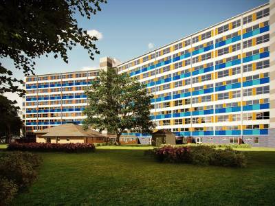
As of the time of writing (March 2016), Block A is nearing completion of the external works, while a significant number of dwellings have remained in occupation, for the most part throughout. Below is a render image of what Block A (left) and Block B (right) will look like upon completion, expected to be later this year (with the completion of Block C in 2017).
In terms of the EuroPHit project, the step-by-step approach, and ensuring that the fabric is upgraded first, the modelling of the proposals in PHPP v9 shows that each block meets the EnerPHit Standard in terms of specific heating demand as follows.
| Block | Treated floor area (m2) | Specific heating demand (kWh/(m2.a) |
| A | 3119.6 | 13 |
| B | 4175.8 | 12 |
| C | 3100.8 | 10 |
Further improvements will be investigated as part of the step by step approach for future implementation, namely replacing the existing electric storage heaters with more efficient models (to further reduce the non-renewable primary energy demand), and also the installation of roof mounted solar photovoltaic panels (to improve the primary energy demand) so that upon completion of the overall refurbishment plan, Wilmcote House will achieve the EnerPHit Standard.
See also
Economic analysis for the retrofit of a detached single family house to the EnerPHit standard
Summary - Using Passive House technology for retrofitting non-residential buildings
Summer situations in refurbished non-residential buildings
| The sole responsibility for the content of Passipedia lies with the authors. While certain marked articles have been created with the support of the EU, they do not necessarily reflect the opinion of the European Union; Neither the EACI nor the European Commission are responsible for any use that may be made of the information contained therein. |


